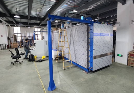
Standard Operating Procedure · Esterilização ETO
This ETO sterilizer operation and maintenance SOP defines how an industrial ethylene oxide sterilizer is operated, maintained, calibrated and validated. It is the document referenced during operator training, routine audits and change control, and it keeps the original controlled structure: Part 1 operação, Part 2 manutenção, Part 3 calibração, Part 4 IR/WH/PQ. Site-specific items are marked as configurable rather than fixed, because not every maintenance or calibration item applies to every installation.
| Prepared by | Checked by | Approved by | Performed by |
|---|---|---|---|
| Hangzhou Bocon | Quality / Validação | User site | Sterilization operator |
Part 1: Operating Instructions
Introduction to the ETO Sterilizer
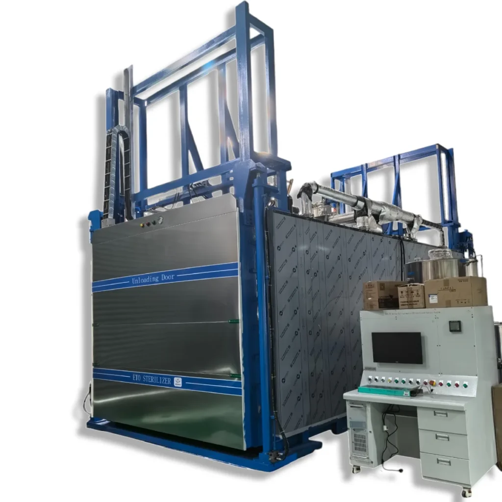
The ETO sterilizer operation and maintenance scope starts with the machine itself. The ethylene oxide sterilizer is used for the disinfection and sterilization of disposable sanitary products, medical products and medical instruments. It must never be used to sterilize or disinfect food. The process is a terminal sterilization method: the load is packaged first and sterilized in its final packaging, so the chamber, the gas distribution and the aeration stage all act on the packaged product.
The control system consists of the electrical control cabinet and the computer operation console. The cabinet contains the operating panel and the low-voltage components — contactors, thermal protectors and similar devices — whose outputs drive the motors, heaters and valves. The console carries the industrial computer, monitor, keyboard, mouse and uninterruptible power supply. Read this document fully and understand the operating and maintenance requirements before the machine is put into use.
Operating the ETO Sterilizer
Before starting the sterilizer, the following safety checks must be completed.
Segurança: no flame work and no unauthorized electrical equipment may be used within 50 m of the sterilization area. Confirm that the exhaust fans are running and that all sensors are in normal working condition before the cycle is started.
- Confirm that no flame work or unauthorized electrical equipment is in use within 50 m of the sterilization area.
- Check that the exhaust fans are running normally.
- Check that all sensors are in normal working condition.
- Select the correct account level before operating; different permission levels correspond to different operator grades.
- Confirm and clear alarm messages before starting a cycle, and monitor for alarms during use.
If an alarm occurs, investigate the cause immediately and assess whether it affects production. Where the effect cannot be excluded, suspend production until the cause is resolved and the cycle can be restarted under control.
Part 2: Maintenance Instructions for the Sterilizer
Purpose of ETO Sterilizer Operation and Maintenance
The maintenance half of this ETO sterilizer operation and maintenance procedure keeps the machine running safely and stably and preserves the safety and effectiveness of the EO sterilization process. Perform the maintenance items defined in this document according to the actual equipment configuration on site; not all items apply to every installation.
Definitions
Daily check. A check, at a defined frequency, that the main components and input/output elements of the sterilizer are in good condition and that the equipment is fit to enter production. Methods include visual inspection, listening, touching, instrument readings and tests; each item should specify the method that suits it.
Preventive maintenance. Planned replacement or servicing of wearing and consumable parts — cleaning, re-tightening, replacement or repair of worn parts, restoration of local accuracy, lubrication system cleaning and oil change, electrical inspection and repair, accuracy adjustment and testing — so that the equipment stays serviceable and does not fail unexpectedly.
Frequencies differ by item and may be monthly, quarterly or annual. Initial frequencies can be based on experience with similar components; later adjustments should be based on maintenance history. Maintenance is also graded: level 1 covers simpler operations performed by front-line operators or maintenance staff; level 2 covers complex work such as dismantling a structurally complex component, which needs a qualified engineer or several people. Level 2 work is normally less frequent.
Repair. The actions needed to restore a damaged part or a degraded function by replacement, repair, adjustment or calibration. A repair may trigger several linked processes: special approval for certain key components; change control, because replacing a key component can require re-validation (IR/WH/PQ); and an assessment, before the repair, of how the functional decline affects the sterilization process, together with the disposition of any nonconforming product and the corrective and preventive actions that follow.
Completeness standard. The equipment is in good working condition when three conditions hold: the mechanical precision stably meets the process requirement and the power equipment meets its specification, running without abnormal noise, over-temperature or over-pressure; parts are complete, safety protection is in place, wear and corrosion are within the specified limits, and the control system, instruments, meters and lubrication system work reliably; and consumption of raw materials, energy and lubricants is normal, with no “four leaks” — oil, water, gas/steam or electricity — and a clean appearance.
Responsabilidades
- The maintainer or sterilization operator performs daily cleaning and inspection and completes the cleaning and inspection records.
- The equipment executive or equipment technician performs daily inspection, repair and maintenance, and completes the maintenance records.
Procedimento
Routine cleaning and checking of the sterilizer and its auxiliary facilities is carried out by the sterilization operator against this procedure, and periodic maintenance is carried out by the maintainer or equipment executive against the same requirements. Both activities are recorded.
Daily cleaning.
- Clean the equipment and the related operating area daily.
- Clean the surface of the electrical control cabinet and control computer daily with a dry rag or brush.
- Clean the walls, the cabinet interior and the door slot daily with a mop and rag, leaving no foreign matter.
- Wipe the mechanical door surface once a week with a rag.
- Clean or remove the compressed air primary filter with a brush every week.
- Clean the inner wall of the circulation fan with an alcohol rag every month.
- Clean the outer and inner surfaces of the sterilizer, the auxiliary piping and the control cabinets thoroughly every month.
Daily checks follow the items, methods and frequencies in Table 2. A check must be completed before restarting after a long idle period, and during continuous production within the same day.
| Não. | Check item | Método | Frequency |
|---|---|---|---|
| 1 | Data display of the temperature sensor, humidity sensor, pressure transmitter and pressure gauge is normal | Visual | Daily |
| 2 | Compressed air pressure is normal, and the value is recorded | Visual | Daily |
| 3 | Seal strip is undamaged and fully bonded to the guide groove | Check / touch | Daily |
| 4 | No gas leakage at the joint between the gas cylinder and the dosing hose | Visual / leak check | Daily |
| 5 | Electronic scale weighs and displays data normally | Visual | Daily |
| 6 | Vaporizer works normally | Check | Daily |
| 7 | Vacuum pump runs normally | Listen / touch / check | Daily |
| 8 | Circulation fan runs normally | Listen / check | Daily |
| 9 | Hot water circulation pump runs normally | Listen / touch / check | Daily |
| 10 | Steam generator is normal | Check | Daily |
| 11 | Actual state of all pneumatic valves matches the control state, i.e. the proportional valve pointer opening agrees with the displayed opening | Check | Daily |
| 12 | Data recorded by the sterilization software matches the set parameters | Check | Weekly |
| 13 | Industrial computer is restarted once a week | Operate | Weekly |
| 14 | Audible and visual alarms of the control system work | Listen / check | Monthly |
| 15 | Steam trap of the humidification steam line operates normally | Check | Monthly |
| 16 | All sensors and monitoring instruments are within their calibration validity | Check | Monthly |
| 17 | Current of the vacuum pump, circulation fan and hot water circulation pump is normal and below the rated value | Test | Monthly |
| 18 | Wiring terminals in the electrical cabinet, control frame and console are secure | Visual | Monthly |
Routine maintenance follows Table 3. Items are preventive: they are scheduled by frequency, not deferred until a failure appears.
| Não. | Item | Método | Frequency | Observação |
|---|---|---|---|---|
| 1 | EO injection pipe and vaporizer | Clean the pipe with nitrogen and drain the vaporizer | Monthly | Prevents pipe clogging |
| 2 | Filter screen of the EO filter | Clean the screen with water | Monthly | Prevents pipe clogging |
| 3 | Vacuum pump | Inject grease through the lubrication nipple with an oil gun | Monthly | Prevents lubrication failure |
| 4 | Vacuum pump | Check and clean the filter of the pump water supply line | Twice per year | Prevents filter blockage that reduces water supply and evacuation rate |
| 5 | Vacuum pump | Check and clean the suction-side filter | Twice per year | Prevents filter blockage that reduces the vacuum rate |
| 6 | EO injection pipe | Steam-clean the dosing pipe every six months | Twice per year | Clean with steam first, then nitrogen |
| 7 | High-efficiency air filter cartridge | Replace | Annual | Blockage reduces the return-air rate and production efficiency; increase frequency if the return rate falls. If the equipment is idle for more than one month, remove and store the cartridge sealed. Maximum replacement interval is one year. |
| 8 | Humidification steam filter cartridge | Replace | Annual | Blockage reduces the humidification rate and production efficiency |
| 9 | Hot water circulation pump | Check the seal ring, water seal and bearing | Annual | Replace the seal ring, water seal and bearing if water leaks; otherwise continue to observe |
| 10 | Door seal | Replace the door seal | Annual | Prevents aging of the seal and loss of chamber tightness |
| 11 | Compressed air / nitrogen tubing | Replace the compressed air and nitrogen lines from the main pipe to the pneumatic valve box, and the air lines connected to the door seal | Annual | Prevents aging and leakage of the tubing |
| 12 | Compressed air / nitrogen tubing | Replace the compressed air and nitrogen lines between the pneumatic valve box and the pneumatic valves | Every three years | Prevents aging and leakage that affects valve switching |
Routine repair.
- Repair equipment failures as soon as possible. If the user cannot handle the fault, report it immediately to the equipment department for assistance.
- Where manufacturer support is required, the equipment department contacts the manufacturer.
- After maintenance, the equipment may only be returned to use after the equipment supervisor and the manufacturer’s maintenance personnel have accepted the work, the equipment engineer and workshop director have confirmed it, and the head of the user department has approved it.
Where an abnormal condition occurs, the maintainer or equipment executive applies the emergency treatment in Table 4.
| Abnormal condition | Cause / influence | Emergency treatment |
|---|---|---|
| Abnormal rate during vacuuming, nitrogen replacement, nitrogen cleaning or air cleaning | Low vacuum pump water supply pressure; high water temperature in the separator chiller; proportional valve fault | Open the water supply valve further for low pressure; top up the water separator; repair or replace the proportional valve |
| Chamber or vaporizer heating time exceeds the normal value | Hot water circulation pump not running; return bypass valve of the pump open | Replace the pump; close the bypass valve promptly |
| Abnormal injection-port temperature during the EO injection stage | Vaporizer hot water circulation pump failure; EO injected too fast; proportional valve not working | Check the pump and the pneumatic valve of the heating line; repair or replace the proportional valve |
| Pressure rises during the exposure stage | Leak in the chamber or in a line connected to it | If the rise exceeds 3 kPa, stop sterilization and enter the cleaning stage; after stopping, check the door valve and the connected lines for leakage |
Leak test procedure. A leak test is required in the following cases:
- The sterilizer has not run for more than 7 dias — test before it is returned to service.
- The sterilizer runs continuously — test once a month.
- The door seal has been replaced.
- The valve and related connection points have been replaced or re-tightened.
The leak test method and acceptance limit are defined in the qualification documentation for the unit. The procedure for performing and recording the test is described in the chamber leak test guide.
Part 3: Measuring Instrument Calibration
Purpose of Calibration
This procedure exists to control measuring instruments so that their monitoring data is valid and continues to meet production requirements. The quality-system basis is ISO 13485:2016, clause 7.6, which requires that equipment used for monitoring and measurement is calibrated or verified at specified intervals against traceable standards.
Escopo
Manage and calibrate the measuring instruments according to the equipment actually installed on site. The calibration table below is a reference scope; not every instrument listed applies to every project.
Definitions
Calibration is the set of operations that establishes, under specified conditions, the relationship between the value indicated by a measuring instrument or measuring system — or the value represented by a material measure or reference material — and the corresponding value realized by a standard.
Responsabilidades
Trained personnel review and collect the calibration standard information, the relevant test data and the calibration reports issued on the certificates, and maintain the annual calibration plan.
Procedimento
Calibration is the third element of ETO sterilizer operation and maintenance: a maintenance programme without traceable instruments only produces confident-looking numbers. The following requirements apply, adapted to the actual instrument list and to customer requirements. The annual plan should be built from the frequencies in Table 5 so that no instrument passes its due date unnoticed.
| Instrument | Equipamento | Calibration points | Acceptance range | Frequency |
|---|---|---|---|---|
| Temperature sensor | Esterilizador | 35 / 54 / 75 °C | ±0.2 °C | Annual |
| Humidity sensor | Esterilizador | 40.0 / 60.0 / 80.0 %RH | ±3 %RH | Twice per year |
| Duct wind speed sensor | Esterilizador | 0.3 / 5.0 / 10.0 / 18.0 m/s | 0.2–5.0 m/s: ±0.2 m/s; 5.0–10 m/s: ±0.3 m/s; >10 m/s: ±0.4 m/s | Annual |
| Pressure transmitter | Esterilizador | −95 / −50 / 0 / 50 / 90 kPa | ±0.5 %FS | Annual |
| Vacuum pressure gauge | Esterilizador | −0.09 / −0.05 / 0.00 / 0.04 / 0.08 / 0.12 / 0.15 MPa | Zero: ±1.6 %FS; 90–100 %FS: ±2.5 %FS; descansar: ±1.6 %FS | Annual |
| Electronic scale | Esterilizador | 2 / 60 / 120 / 180 / 240 / 300 kg | ±100 g | Annual |
| Steam pressure gauge | Esterilizador | 0 / 0.4 / 0.8 / 1.2 MPa | Zero: ±1.6 %FS; 90–100 %FS: ±2.5 %FS; descansar: ±1.6 %FS | Annual |
| EO concentration sensor | Esterilizador | 250 / 500 / 750 mg/L | ±60 mg/L | Quarterly |
| Vacuum pressure gauge | Nitrogen generator | 0 / 0.4 / 0.8 / 1.2 MPa | Zero: ±1.6 %FS; 90–100 %FS: ±2.5 %FS; descansar: ±1.6 %FS | Annual |
| Nitrogen purity analyser | Nitrogen generator | 80 / 89 / 95 / 100 % | ±1 % | Annual |
| Space temperature sensor | Precondition room | 30.0 / 45.0 / 60.0 °C | ±0.2 °C | Annual |
| Space humidity sensor | Precondition room | 15 / 20 / 30 / 40 / 60 / 80 %RH | ±3 %RH | Annual |
| Supply air temperature sensor | Precondition room | 20 / 40 / 60 °C | ±1 °C | Annual |
| Supply air wind speed sensor | Precondition room | 2.0 / 5.0 / 10.0 / 15.0 m/s | 0.2–5.0 m/s: ±0.2 m/s; 5.0–10 m/s: ±0.3 m/s; >10 m/s: ±0.4 m/s | Annual |
| Load temperature sensor | Precondition room | 15.0 / 40.0 / 60.0 °C | ±1 °C | Annual |
| Space temperature sensor | Heated aeration room | 20 / 40 / 60 °C | ±0.2 °C | Annual |
| Supply air temperature sensor | Heated aeration room | 20 / 40 / 60 °C | ±1 °C | Annual |
| Wind speed sensor | Heated aeration room | 2.0 / 5.0 / 10.0 / 15.0 m/s | 0.2–5.0 m/s: ±0.2 m/s; 5.0–10 m/s: ±0.3 m/s; >10 m/s: ±0.4 m/s | Annual |
| Intelligent temperature controller | Incubadora | 37.0 °C | Lower limit 36.0°C; upper limit 38.0°C | Annual |
| Temperature recorder | Incubadora | 30 / 35 / 40 °C | ±1 °C | Annual |
| Temperature controller | Sealing machine | 50 / 100 / 200 / 300 °C | ±1 °C | Annual |
| Temperature and humidity meter | Reference instrument | 5 / 25 / 45 °C | ±1 °C | Annual |
| Anemometer | Reference instrument | 5.0 / 15.0 / 25.0 / 35.0 / 45.0 m/s | ±3 %FS | Annual |
| Surface thermometer | Reference instrument | 20 / 40 / 60 °C | ±2.5 %FS | Annual |
Part 4: QI / QO / PQ Validation Requirements
Purpose of Validation
Validation closes the ETO sterilizer operation and maintenance loop: the SOP is only credible if the equipment has been shown to work as installed. The purpose is to obtain evidence that the equipment used for ETO sterilization has been supplied and installed in accordance with its specification, operates stably within predetermined limits, and consistently performs according to predetermined criteria so that the product meets its specification. This part defines the requirements for development, validation and routine control of the ETO sterilization process, in line with ISO 11135 and the relevant regulatory expectations for installation, operational and performance qualification.
Escopo
The relevant equipment used in ETO sterilization: precondition room, sterilizer, aeration room, incubator and the associated monitoring instruments.
Termos e Definições
- Installation qualification (QI): evidence that the equipment and ancillary items were supplied and installed as specified.
- Operational qualification (QO): evidence that the installed equipment performs within its defined operating limits.
- Performance qualification (QP): microbiological PQ (MPQ) and physical PQ (PPQ), demonstrating the process delivers the required SAL to the load.
- Requalification: repeat of the qualification activity at a defined interval or after a defined change.
- Carga biológica: the population of viable microorganisms on or in a product before sterilization.
- Biological indicator (BI): a prepared inoculum of a defined microorganism used to demonstrate the lethality of the process.
- Fractional cycle: a cycle used to demonstrate the resistance of the product bioburden relative to the process challenge.
- Half cycle: a cycle delivering half the routine exposure, used to prove reproducibility of the process.
- Full cycle: the routine process specification, including exposure and aeration.
- Process challenge device (PCD): a device that presents a defined challenge to the sterilizing process; internal (IPCD) and external (EPCD) variants are used together.
- Product and product family: the item to be sterilized, and a group of items shown to be equivalent for validation purposes.
- Usable volume and product load volume: the chamber volume available for the load, and the volume actually occupied by product.
- Sterility and sterility assurance level (SAL): the state of being free from viable microorganisms, and the probability of a microorganism surviving sterilization.
Responsabilidades
The sterilization validation engineer drafts the validation protocol. Trained personnel and the user perform the validation, collect the relevant data and assist in completing the validation report.
Procedimento
Installation qualification. IQ demonstrates that the sterilization equipment and any ancillary items have been supplied and installed in accordance with their specification. Before IQ, the equipment manufacturer performs FAT and SAT to confirm that the equipment has been delivered normally. During IQ the following are identified and substantiated:
- The equipment used in the sterilization process, including ancillary items, complies with its design specification; the corresponding documents include the functional design specification, user requirements specification and design drawings (equipment schematic, energy supply diagram, electrical schematic and system schematic).
- All components, including control software, function correctly; key measuring instruments are calibrated; key component information is recorded.
- The installation and use environment is safe and complies with local regulations, including safety and personnel health requirements.
- Safety production and operating procedures exist, including maintenance documents and exception handling documents; operators are trained and only start work after qualifying.
IQ may be a one-time exercise for the specific equipment used in a sterilization process. Additional IQ is required after significant component or functional changes, and after a change of location.
Operational qualification. OQ demonstrates the ability of the equipment to meet the performance requirements of its design specification. During OQ the following are identified and substantiated:
- The performance of the relevant auxiliary systems is determined, and the software system is tested by simulating fault conditions.
- For the precondition room, sterilizer and aeration room, the air circulation pattern and ventilation capacity throughout the chamber volume occupied by the load are determined, for example by smoke tests combined with air-change-rate calculations and anemometer readings.
- Temperature and humidity are monitored throughout the preconditioning area, at several distributed locations and over a period long enough to show that values stay within the desired ranges.
- Temperature is monitored throughout the heated aeration area at several distributed locations, over a period long enough to show that values stay within the desired ranges.
- The sterilizer passes a leak test before OQ — under vacuum for subatmospheric cycles, or under vacuum and at pressure for superatmospheric cycles.
- A chamber wall temperature study is completed to verify that the jacket heating system provides adequate temperature uniformity; the study characterizes the temperature profile so that it can be compared periodically and the system shown to remain effective.
- Repetition cycles are performed at least three times to demonstrate reproducibility of control and operation; the temperature of the injected EO gas is within the vaporizer specification or above the boiling point of EO at atmospheric pressure.
- In empty-chamber OQ, after an equilibration period, the recorded temperature within the usable chamber volume during EO or inert gas exposure stays within ±3 °C of the average recorded chamber temperature at each time point. When OQ is carried out with a loaded chamber, o ±3 °C tolerance may not be achievable.
Annual OQ. The review of OQ includes an assessment of equipment performance and of the engineering changes made during the year, to confirm that the original OQ results remain valid. Periodic requalification normally covers:
- Review of the IQ status of the equipment.
- Assessment of trends in equipment performance.
- Temperature and humidity profiles of the preconditioning areas.
- Chamber temperature profile.
- Temperature profile of the aeration room.
Performance qualification. PQ demonstrates that the equipment consistently operates in accordance with predetermined acceptance criteria and that the process yields sterile product meeting the specified requirements. It is carried out for each new process or product to be validated, consists of both microbiological and physical performance qualification, and is performed in the equipment used to sterilize the product.
- The product packaging and loading mode are specified; representative products or materials are selected so that their packaging and material composition cover the whole product range or product family.
- The load is representative of routine production and is defined from the most challenging routine load; changes in load configuration can affect the lethality of the process.
- The process and its effect are monitored through physical parameters and through the growth of BI/PCD during sterilization.
- MPQ and PPQ are generally performed simultaneously. If PPQ runs in parallel with at least three MPQ runs, a minimum of one additional PPQ run is performed using the full-cycle process specification. PPQ demonstrates that the acceptance criteria are met throughout the load for the duration of the proposed routine process.
- PQ is repeated on the introduction of new or modified products, embalagem, load configuration, equipment or process parameters, unless equivalence to a previously validated configuration has been documented.
The PQ verification sequence is generally as follows:
- Perform a fractional cycle and test the sterility status of the product afterwards; compare the EO resistance relationship between IPCD, EPCD and the representative product, with the expected order EPCD > IPCD > product. The test requirements for the fractional cycle refer to ISO 11737-2.
- Perform a half cycle to prove the reproducibility of the sterilization process and its effect. If the overkill method is used, there should be no positive IPCD during the half cycle. Positive EPCD during the half cycle is acceptable where the EPCD has been shown to be more resistant than the IPCD, providing a worst-case challenge for routine processing.
- Routine sterilization parameters are usually determined by the full-cycle parameters, so residual challenges are generally addressed during the full cycle to determine the appropriate aeration time. Because effectiveness has been demonstrated in the fractional and half cycles, the sterilization effect can be assured through the EPCD.
If sterility or product functionality requirements are not met in any run, an investigation determines whether additional qualification runs are necessary. If process parameters cannot be maintained within the defined limits, an investigation is conducted, and any modification requires additional runs.
Annual PQ. The review of PQ assesses that the sterilization process remains valid for the designated product. Reduced MPQ/PPQ may be necessary in certain situations, for example to verify that the resistance of the internal PCD in the product load remains appropriate relative to the product bioburden, ou, after a defined interval, to provide evidence that no inadvertent change has occurred since the previous requalification. This would typically include at least one fractional or half-cycle exposure with load temperature and humidity measurements. Fractional cycles in a development chamber can support a requalification programme, but requalification of the production chamber should be performed in the production chamber.
Need an SOP That Matches Your Installed Configuration?
Send your equipment list, instrument schedule and current validation status. Our engineers return an ETO sterilizer operation and maintenance package — a site-specific SOP outline, a calibration plan and a gap list against ISO 11135 e ISO 13485 clause 7.6.
Chat with an Engineer on WhatsApp Request a Technical ProposalReferência: ISO 11135:2014 · ISO 13485:2016 clause 7.6 · ISO 11737-2 · EM 1422. Site-specific values follow the approved SOP and calibration schedule for each installation.