Panduan Pemilihan dan Konfigurasi Teknikal Langkah demi Langkah untuk Sistem Pensteril EtO
An engineering blueprint for calculating capacity, choosing parameters, and designing fully compliant medical device sterilization workshops.
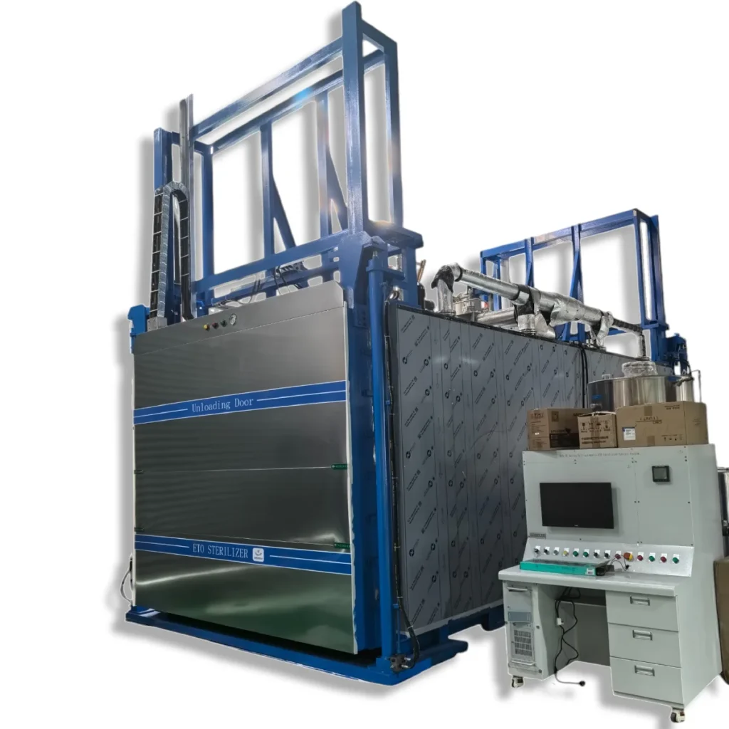
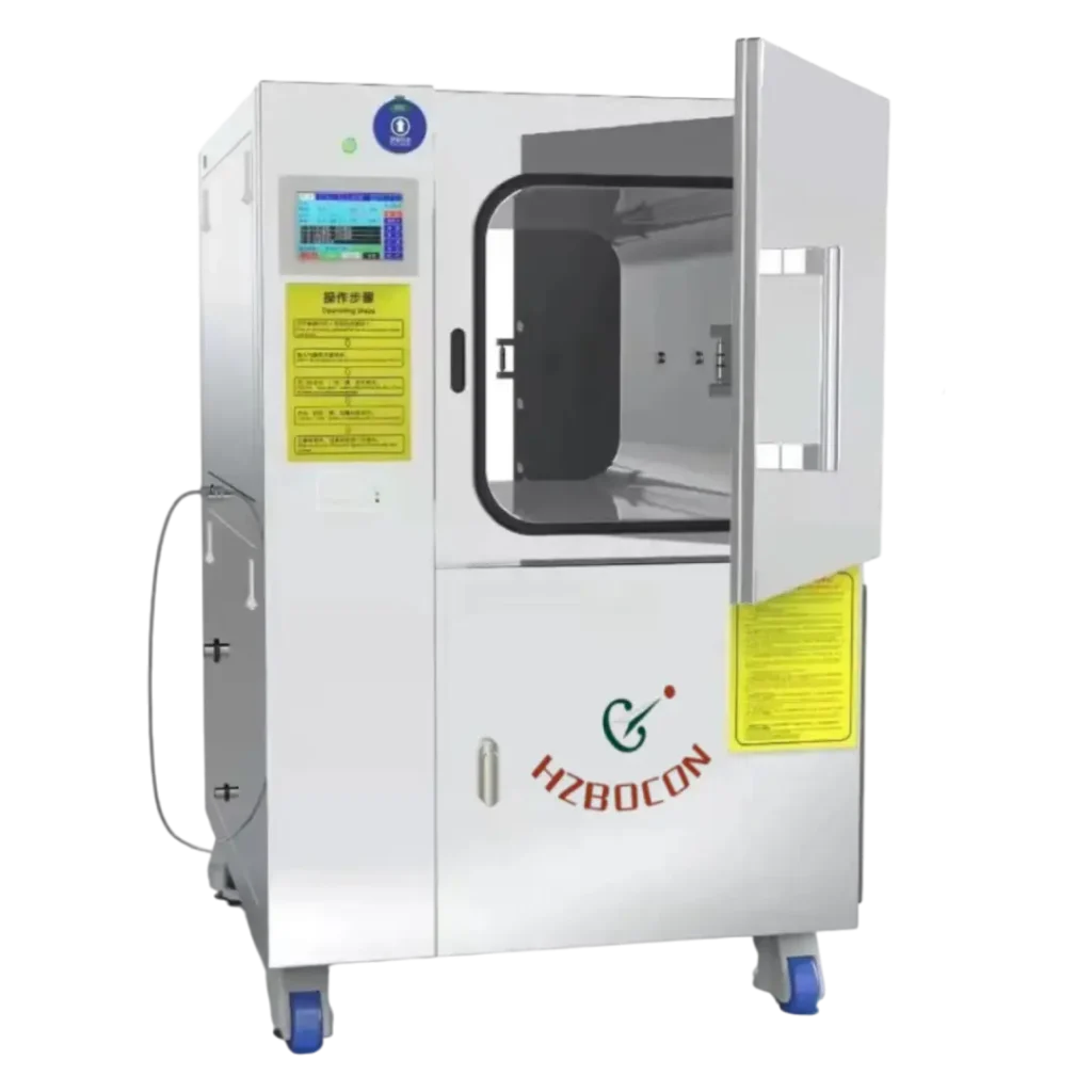
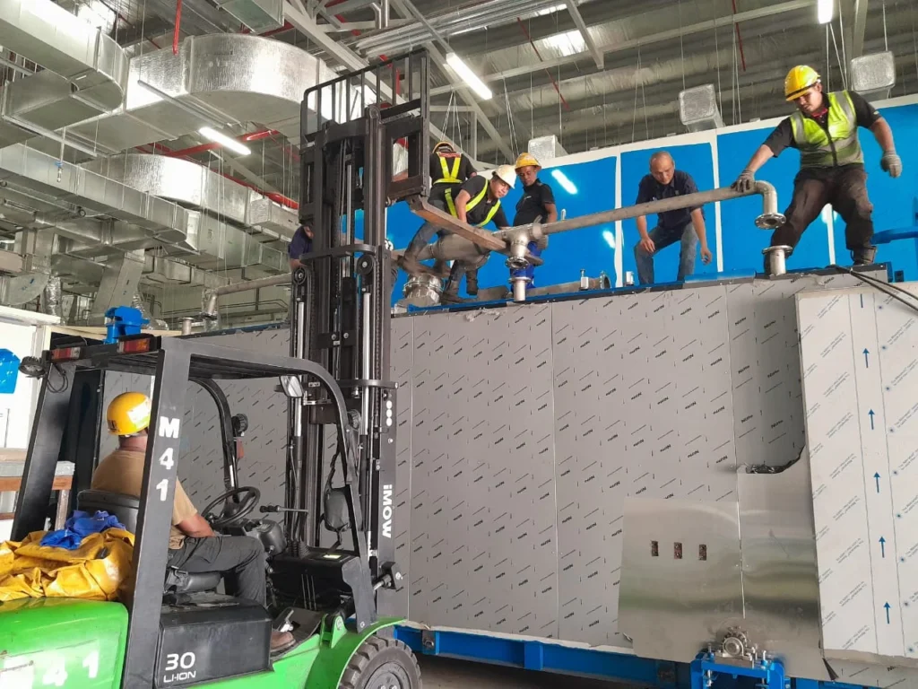
Implementing an industrial industrial EtO sterilizer machine requires careful engineering evaluation. From calculating raw loading capacities to establishing multi-layered plant safety controls, each phase determines production efficiency and regulatory compliance. This comprehensive technical guide outlines the critical steps required to configure an industrial EtO sterilization plant successfully.
Step 1. Calculate the Chamber Capacity of the Sterilizer
The baseline sizing of an industrial sterilizer depends entirely on your daily throughput demands and packaging geometry:
- The Volumetric Loading Factor: The actual loading efficiency of an Ethylene Oxide sterilizer chamber is approximately 70% due to airflow gaps and pallet positioning. For instance, a standard 10 cubic meter sterilizer effectively processes 7 cubic meters of packaged medical products per batch.
- Cycle Throughput Dynamics: A complete chemical sterilization run typically takes 8 to 10 jam. Consequently, a properly managed facility can achieve two complete sterilization cycles per day. Note that the precise sterilization duration is strictly dictated by Performance Qualification (PQ) validation protocols.
- Pallet Dimension Standards: Chamber floor guide tracks and internal dimensions are engineered around localized supply chain pallets. Industry-standard configurations utilize dimensions such as 800mm × 1200mm, 1000mm × 1200mm, or 1100mm × 1100mm.

Step 2. Determine the Technical Function and Configuration of the EtO Sterilizer
Once your chamber footprint is locked in, the core mechanical, gas-handling, and electrical parameters must be specified based on process criteria:
A. Electrical Infrastructure Matching
Industrial power distribution grids vary by geographical market. Control systems must be wound and certified to match local utilities, with standard selections including 380V/50Hz, 380V/60Hz, 415V/50Hz, or 440V/60Hz. Voltage stabilization transformers can be integrated for facilities with unstable electrical supplies.
B. Ethylene Oxide Gas Concentration Percentage
The choice of active sterilant concentration depends heavily on product chemical resistance, local gas availability, and gas supplier sourcing:
- Pure vs. Blended Gas Systems: Equipment can be configured for 100% pure EO, or customized for diluted, non-flammable gas mixtures such as 90%EO+10%CO2, 80%EO+20%CO2, 70%EO+30%CO2, 30%EO+70%CO2, 20%EO+80%CO2, or 10%EO+90%CO2.
- Process Implications: Lower gas concentrations naturally require higher working pressures to achieve equivalent lethal mass transfer, which alters required chamber pressure ratings but can shorten post-cycle aeration times.
- Nitrogen Blanketing Requirements: Processes utilizing active gas concentrations above 80% mandate the integration of nitrogen injection systems to maintain safety boundaries, requiring a dedicated external nitrogen generator. Standard industry operations often fall within the 70% to 30% EO range.
C. Environmental Boundaries (Kelembapan & Temperature Range)
- Humidity Controls: The default system envelope operates between 30%RH and 80%RH. Specialized medical devices, such as absorbable or non-absorbable surgical sutures, require tailored microclimates utilizing dry vacuum pumps paired with heavy nitrogen blanketing to restrict moisture overhead.
- Temperature Range: The structural heating jacket regulates internal conditions across a standard baseline of 30°C to 55°C, with a maximum processing ceiling limited below 58°C.

D. Mechanical Architecture & Containment Materials
- Door Mechanics: Access configurations are selected based on plant layout restrictions and floor space availability. Choices include sliding doors (which require wider lateral workshop spacing), revolving doors, or vertical lifting doors (engineered to minimize floor footprints in tall ceiling facilities). Systems can be specified as single-door or double-door pass-through designs.
- Chamber Water Jacket Materials: To guarantee long-term thermal conduction and prevent jacket breakdown, structural material selections include Carbon Steel (offering a service life exceeding 20 years), or high-tier 201 Stainless Steel and 304 Stainless Steel (extending operational lifespans beyond 30 years).
E. Pematuhan Peraturan, Parameter Release, and Specialized Add-ons
For high-performance facilities transitioning toward parametric release instead of traditional Biological Indicator (BI) incubation, yang industrial EtO sterilizer machine incorporates secondary isolated internal sensors for direct gas concentration and internal humidity verification. To secure full compliance with strict global standards like FDA 21 CFR Part 11, the system integrates the following automated fail-safes:
- Auxiliary Industrial PC (Backup IPC): Eliminates data loss risks during runtime communication drops.
- Online Concentration Monitoring: Continuous real-time analysis of gas levels inside the vessel.
- Redundant Vacuum Architecture: Secondary backup vacuum pump loops for emergency extraction.
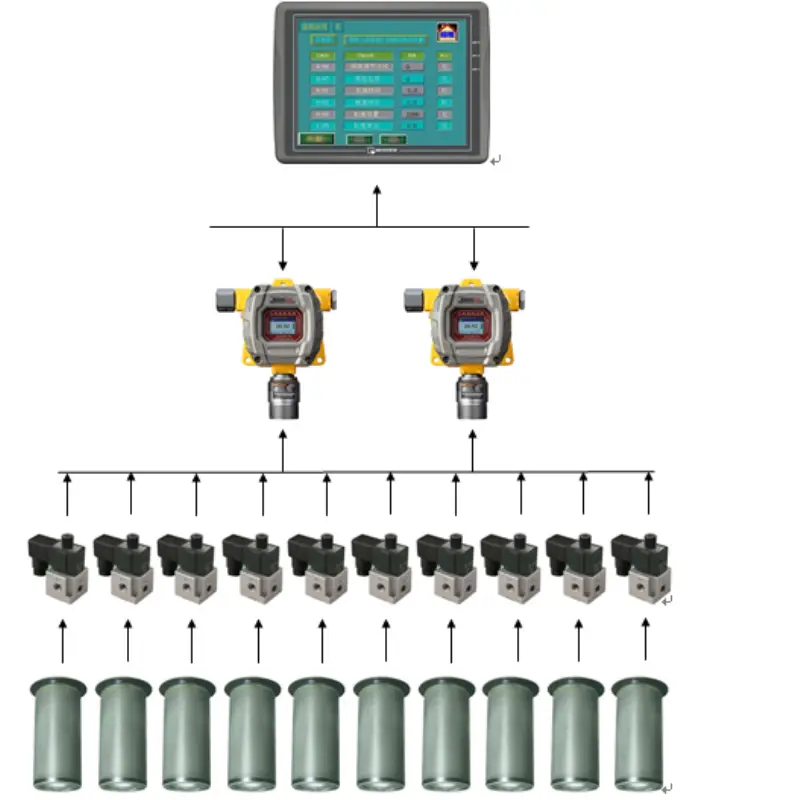
- Ambient Gas Safety Arrays: Integrated facility gas monitors sampling up to 8 distinct workshop perimeter points.
- Automated Conveyor Devices: In regions where worker occupational protection codes prohibit entry into chemical processing vessels, automated internal conveyor mechanisms load and unload products safely without manual handling.

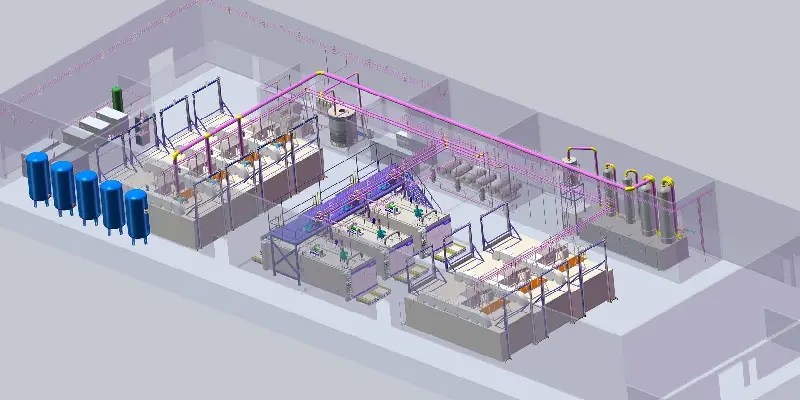
Steps 3 & 4. Process Decoupling: Preconditioning and Aeration Design
An industrial sterilization cycle requires three distinct thermodynamic phases: heating/humidification, gas exposure, and residual degassing. These can occur within a single unified chamber or be split across distinct rooms to maximize equipment utilization:
Step 3. The Precondition Room
A separate preconditioning cell heats and humidifies products before they enter the main sterilizer. This step allows the sterilizer chamber to focus exclusively on active gas exposure, drastically shortening the total vessel cycle time. Without a preconditioning cell, products must undergo these preparation phases directly inside the primary sterilizer vessel.

Step 4. The Aeration (Degassing) Room
Post-exposure, residual gaseous molecules must desorb from the product matrix until they drop to safe parts-per-million (ppm) levels. Global regulatory standards dictate that final residual gas concentrations cannot exceed 10ppm (10µg/g) at the time of factory dispatch. Three process paths can achieve this goal:
- Option A (Dedicated Aeration Room): Products are transferred to an isolated, heated degassing cell for 1 to 2 hari. This configuration is strongly recommended for high-retention products such as medical syringes, prolonged-use catheters, and surgical gloves.
- Option B (Chamber In-situ Aeration): Residual extraction occurs directly inside the primary sterilizer chamber. While highly secure, this method holds the product within the vessel for 24 hours or longer, requiring an expanded total sterilizer volume to meet plant output quotas.
- Option C (Natural Warehouse Ventilation): Storing products in a well-ventilated open warehouse zone for a natural desorption period of 14 to 20 hari. This method carries high quality-control risks regarding irregular residual concentrations.
Steps 5 & 6. Utilities and Abatement Infrastructure
Step 5. Nitrogen Generator Integration
High-purity nitrogen serves two crucial process roles: purging moisture out of moisture-sensitive packages and inerting the environment during gas transitions. For recipes with gas compositions exceeding 80% EO, nitrogen blanketing is essential to prevent explosive mixtures from forming inside the pressure vessel.
Step 6. EO Waste Gas Treatment Systems (Catalytic / Scrubber Systems)
Environmental emissions must pass through dedicated treatment apparatuses before atmospheric discharge. Wet scrubber systems leverage the natural affinity of Ethylene Oxide to mix with water. Under precise acidic conditions induced by a sulfuric acid catalyst, the toxic gas undergoes chemical hydrolysis to form stable ethylene glycol, which is then neutralized with alkali back to a safe pH of approximately 7.
C₂H₄O + H₂O —→ CH₂OH-CH₂OH
Scrubber columns are fabricated using heavy corrosion-resistant materials such as Polypropylene Homopolymer (PPH), Fiber Reinforced Plastic (FRP), atau 304 Stainless Steel. Discharge configurations can be customized to comply with localized environmental targets, matching strict global limits such as 80mg/Nm³ (44ppm), 40mg/Nm³ (22ppm), 5mg/Nm³ (3ppm), or 1mg/Nm³ (0.5ppm).

Step 7. Layout and Preparation of Workshop Conditions for Sterilization
The structural layout of an active sterilization facility requires clear separation of processing areas to comply with international manufacturing codes:
- Zonal Isolation Rules: A standard facility must maintain an isolated EO Gas Storage Room, an Auxiliary Equipment Room, and a distinct Control Room. Regulatory standards dictate that doors exiting the primary EO Gas Room must never open directly into general assembly or manufacturing workshops.
- Explosion Protection & Ventilation: Open flames are strictly prohibited throughout the entire footprint. The gas room must be equipped with specialized explosion-proof lighting fixtures, isolated switchgear, and dedicated sparkless axial flow extraction fans positioned 300mm to 500mm above the floor line to capture heavy settling gases.
- Environmental & Height Preconditions: The facility floor plan must provide an absolute minimum ceiling clearance height of 3000mm. Additionally, the building envelope must maintain a steady ambient temperature above 10°C, requiring active climate heating systems during winter operation to ensure stable process lines.

Streamline Your Medical Device Compliance Today
Ready to configure an ISO 11135 compliant facility? Contact BOCON’s engineering team for free custom 3D plant layouts, process optimization, and turnkey structural system blueprints tailored to your medical production line.